Monday 1 July 2019

Physical layer of OSI model

Physical layer in the OSI model plays the role of interacting with actual hardware and signaling mechanism. Physical layer is the only layer of OSI network model which actually deals with the physical connectivity of two different stations. This layer defines the hardware equipment, cabling, wiring, frequencies, pulses used to represent binary signals etc.
Physical layer provides its services to Data-link layer. Data-link layer hands over frames to physical layer. Physical layer converts them to electrical pulses, which represent binary data.The binary data is then sent over the wired or wireless media.

Signals

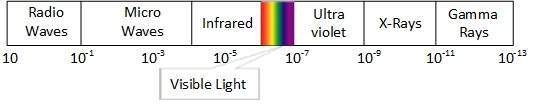
When data is sent over physical medium, it needs to be first converted into electromagnetic signals. Data itself can be analog such as human voice, or digital such as file on the disk.Both analog and digital data can be represented in digital or analog signals.
  • Digital Signals
    Digital signals are discrete in nature and represent sequence of voltage pulses. Digital signals are used within the circuitry of a computer system.
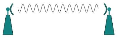
  • Analog Signals
    Analog signals are in continuous wave form in nature and represented by continuous electromagnetic waves.

Transmission Impairment

When signals travel through the medium they tend to deteriorate. This may have many reasons as given:
  • Attenuation
    For the receiver to interpret the data accurately, the signal must be sufficiently strong.When the signal passes through the medium, it tends to get weaker.As it covers distance, it loses strength.
  • Dispersion
    As signal travels through the media, it tends to spread and overlaps. The amount of dispersion depends upon the frequency used.
  • Delay distortion
    Signals are sent over media with pre-defined speed and frequency. If the signal speed and frequency do not match, there are possibilities that signal reaches destination in arbitrary fashion. In digital media, this is very critical that some bits reach earlier than the previously sent ones.
  • Noise
    Random disturbance or fluctuation in analog or digital signal is said to be Noise in signal, which may distort the actual information being carried. Noise can be characterized in one of the following class:
    • Thermal Noise
      Heat agitates the electronic conductors of a medium which may introduce noise in the media. Up to a certain level, thermal noise is unavoidable.
    • Intermodulation
      When multiple frequencies share a medium, their interference can cause noise in the medium. Intermodulation noise occurs if two different frequencies are sharing a medium and one of them has excessive strength or the component itself is not functioning properly, then the resultant frequency may not be delivered as expected.
    • Crosstalk
      This sort of noise happens when a foreign signal enters into the media. This is because signal in one medium affects the signal of second medium.
    • Impulse
      This noise is introduced because of irregular disturbances such as lightening, electricity, short-circuit, or faulty components. Digital data is mostly affected by this sort of noise.

Transmission Media

The media over which the information between two computer systems is sent, called transmission media. Transmission media comes in two forms.
  • Guided Media
    All communication wires/cables are guided media, such as UTP, coaxial cables, and fiber Optics. In this media, the sender and receiver are directly connected and the information is send (guided) through it.
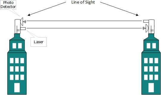
  • Unguided Media
    Wireless or open air space is said to be unguided media, because there is no connectivity between the sender and receiver. Information is spread over the air, and anyone including the actual recipient may collect the information.

Channel Capacity

The speed of transmission of information is said to be the channel capacity. We count it as data rate in digital world. It depends on numerous factors such as:
  • Bandwidth:  The physical limitation of underlying media.
  • Error-rate:  Incorrect reception of information because of noise.
  • Encoding:  The number of levels used for signaling.

Multiplexing

Multiplexing is a technique to mix and send multiple data streams over a single medium. This technique requires system hardware called multiplexer (MUX) for multiplexing the streams and sending them on a medium, and de-multiplexer (DMUX) which takes information from the medium and distributes to different destinations.
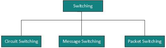
Switching

Switching is a mechanism by which data/information sent from source towards destination which are not directly connected. Networks have interconnecting devices, which receives data from directly connected sources, stores data, analyze it and then forwards to the next interconnecting device closest to the destination.
Switching can be categorized as:
Switching

Frequency Ranges


Have you ever wondered how your television and mobile phone can work at the same time? Both receive signals via antenna in the form of electromagnetic waves but don't interfere with each other. The reason is that all wireless devices operate in their own frequency bands within which they transmit and receive signals. For example, television broadcast operates between 54-216 MHz, FM radio operates between 87.5-108 MHz and cell phones operate either between 824-894 MHz or 1850-1990 MHz.

Frequency Band NameFrequency RangeApplication
Extremely Low Frequency (ELF)3-30 HzUnderwater Communication
Super Low Frequency (SLF)30-300 HzAC Power
Very Low Frequency (VLF)3-30 kHzFor Navigation Alarms
Low Frequency (LF)30-300 kHzAM Radio
Medium Frequency (MF)300-3000 kHzAviation
High Frequency (HF)3-30 MHzShortwave Radio
Very High Frequency (VHF)30-300 MHzFM Radio
Ultra High Frequency (UHF)300-3000 MHzTelevision, mobile phones, GPS
Super High Frequency (SHF)3-30 GHzSatellite, Wireless Communication
Extremely High Frequency (EHF)30-300 GHzRemote Sensing, Astronomy

Wireless transmission

Wireless transmission is a form of unguided media. Wireless communication involves no physical link established between two or more devices, communicating wirelessly. Wireless signals are spread over in the air and are received and interpreted by appropriate antennas.
When an antenna is attached to electrical circuit of a computer or wireless device, it converts the digital data into wireless signals and spread all over within its frequency range. The receptor on the other end receives these signals and converts them back to digital data.
A little part of electromagnetic spectrum can be used for wireless transmission.
Electromagnetic Spectrum

Radio Transmission

Radio frequency is easier to generate and because of its large wavelength it can penetrate through walls and structures alike.Radio waves can have wavelength from 1 mm – 100,000 km and have frequency ranging from 3 Hz (Extremely Low Frequency) to 300 GHz (Extremely High Frequency). Radio frequencies are sub-divided into six bands.
Radio waves at lower frequencies can travel through walls whereas higher RF can travel in straight line and bounce back.The power of low frequency waves decreases sharply as they cover long distance. High frequency radio waves have more power.
Lower frequencies such as VLF, LF, MF bands can travel on the ground up to 1000 kilometers, over the earth’s surface.
Radio wave - grounded
Radio waves of high frequencies are prone to be absorbed by rain and other obstacles. They use Ionosphere of earth atmosphere. High frequency radio waves such as HF and VHF bands are spread upwards. When they reach Ionosphere, they are refracted back to the earth.
Radio wave - Ionosphere

Microwave Transmission

Electromagnetic waves above 100 MHz tend to travel in a straight line and signals over them can be sent by beaming those waves towards one particular station. Because Microwaves travels in straight lines, both sender and receiver must be aligned to be strictly in line-of-sight.
Microwaves can have wavelength ranging from 1 mm – 1 meter and frequency ranging from 300 MHz to 300 GHz.
Personal Area Network
Microwave antennas concentrate the waves making a beam of it. As shown in picture above, multiple antennas can be aligned to reach farther. Microwaves have higher frequencies and do not penetrate wall like obstacles.
Microwave transmission depends highly upon the weather conditions and the frequency it is using.

Infrared Transmission

Infrared wave lies in between visible light spectrum and microwaves. It has wavelength of 700-nm to 1-mm and frequency ranges from 300-GHz to 430-THz.
Infrared wave is used for very short range communication purposes such as television and it’s remote. Infrared travels in a straight line hence it is directional by nature. Because of high frequency range, Infrared cannot cross wall-like obstacles.

Light Transmission

Highest most electromagnetic spectrum which can be used for data transmission is light or optical signaling. This is achieved by means of LASER.
Because of frequency light uses, it tends to travel strictly in straight line.Hence the sender and receiver must be in the line-of-sight. Because laser transmission is unidirectional, at both ends of communication the laser and the photo-detector needs to be installed. Laser beam is generally 1mm wide hence it is a work of precision to align two far receptors each pointing to lasers source.
Light Transmission
Laser works as Tx (transmitter) and photo-detectors works as Rx (receiver).
Lasers cannot penetrate obstacles such as walls, rain, and thick fog. Additionally, laser beam is distorted by wind, atmosphere temperature, or variation in temperature in the path.
Laser is safe for data transmission as it is very difficult to tap 1mm wide laser without interrupting the communication channel.